Standards
General Tab

| Setting | Description |
|---|---|
| Profile | Set the naming format for drawing files. Select a pre-defined profile or click Edit to modify the elements of existing profiles. The Drawing Naming Convention dialog displays allowing you to define the naming format for the drawing files. |
| Electrical Standard | Select whether the drawings will follow the ANSI-IEEE or IEC standard. |
| Default Units of Measure | Select whether your drawings will use Inches or Metric(mm) as the standard units. These units will also be used for report templates. |
| Device Appending Setting |
Allow Devices To Be Appended To Families - Enable to allow additional symbols to be assigned to a device ID after the available spots have been filled. If you select this option, then the following two options become available: These options determine whether parent symbols, child symbols or both can be appended. |
| Primary Mode | Allows user to designate a drawing mode as primary which means an ID assigned in that mode will replace a different ID assigned to the same device in another mode. |
Grid/Snap Settings Tab
The Default Grid Settings mode allows user to set grid and snap spacing for various types of drawings. Most Bentley Substation drawing modes utilize a grid that causes objects to be aligned properly. For example, the grid ensures that wires make contact with symbol connection points so that the software can recognize these connections. Snap mode causes the cursor to limit its movements to set increments. The user can adjust the spacing of the grid and snap mode to suit his requirements.
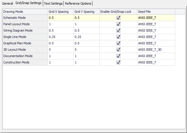
| Setting | Description |
|---|---|
| X,Y Grid/Snap Spacing | Sets the X and Y grid line spacing and snap mode intervals for various types of drawings. Enter the desired values for each drawing mode. |
| Enable Grid/Snap Lock | When enabled for a drawing mode, the snap-to-grid feature will be turned on automatically when you place or move items in a drawing. |
| Seed File | The Seed File column specifies the name of a seed file for each drawing mode. The seed file is a drawing template file located in the Standards\Substation\Templates\Page folder. It contains setting information that determine default units that will be used in the drawing. To change the seed file, click inside the Seed File field and make a selection from the drop-down list of seed files that appears. When you change the seed file setting, it will only affect pages that are created after the change is made. |
Text Settings Tab
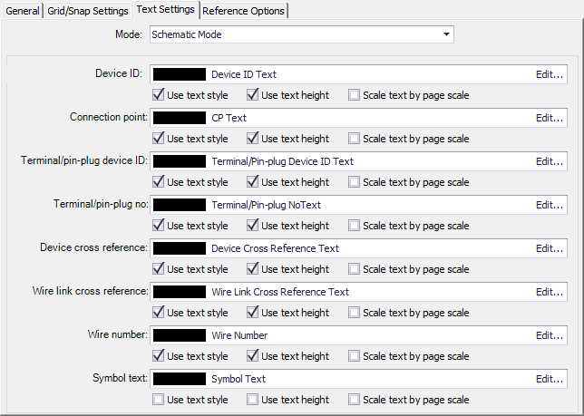
Fields for different categories of text (IDs, wire numbers, cross references, etc.) are provided. For each field, there are three check boxes:
| Setting | Description |
|---|---|
| Use text style | If you select Use text style, the software will use the text values defined in the text style for that type of text. If you de-select this check box, the software will use the text settings that were defined in the symbol or in the wire numbering function for subsequently inserted symbols and assigned wire numbers. |
| Use text height | If you select Use text height, the software will use the text height defined in the text style for that type of text. If you de-select this check box, the software will use the text height that was defined in the symbol or in the wire numbering function for subsequently inserted symbols and assigned wire numbers. |
| Scale text by page scale | If you select Scale Text By Page Scale, the software will scale the text size according to the page scale for the current page. |
If you wish to modify any of the text styles, select the Edit button for the desired text type. The following dialog displays:

| Setting | Description |
|---|---|
| Profile Name | List the name of the current profile. |
| Save Profile | Saves the profile settings to the project for future use. |
| Load Profile | Click this to recall a saved profile. |
| Font Name | Select a font from the drop-down list. |
| Height | Sets the text height. |
| Preview | An example of how the current font settings will appear. |
| Width Factor | Sets character spacing. Entering a value of less than 1.0 condenses the text. Values greater than 1.0 expand the text. |
| Rotate | Enter an angle value for placing text on a page. |
| Oblique | Sets the oblique angle (italicizing) of the text. Enter a value between -85 and 85. |
| Color | Select a color for the text from the drop-down list. Use the Browse button to open a color dialog for additional colors. |
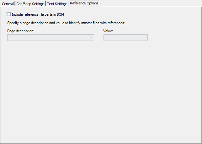
Reference Options Tab
| Setting | Description |
|---|---|
| Include reference file parts in BOM | Enable this check box to include reference file parts in Bills of Material. |
| Specify a page description and value to identify master files with references | If you enabled the Include reference file parts in BOM check box, specify the page description and value in the respective fields. |